Toyota Corolla Manual de Taller: Datos De Imagen Fija

DATOS DE IMAGEN FIJA

DESCRIPCIÓN

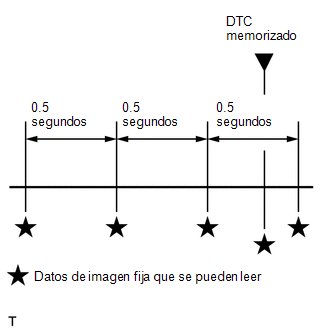
El ECM registra información sobre las condiciones de conducción y el estado del vehículo como datos de imagen fija en el momento de memorizar un DTC. Cuando se realiza la localización de averías, los datos de imagen fija pueden ser útiles para determinar si el vehículo estaba en movimiento o parado, si el motor estaba caliente o no, si la relación aire/combustible era pobre o rica, así como otros datos registrados en el momento en que se produjo la anomalía.

OBSERVACIÓN:

Si no es posible reproducir el problema aunque se detecte el DTC, verifique los datos de imagen fija.

El ECM registra el estado del motor en forma de datos de imagen fija cada 0.5 segundos. Con el Techstream se pueden comprobar 5 grupos separados de datos de imagen fija.

  • 3 conjuntos de datos antes de que se almacenara el DTC.
  • 1 conjunto de datos al almacenarse el DTC.
  • 1 conjunto de datos posterior al almacenamiento del DTC.

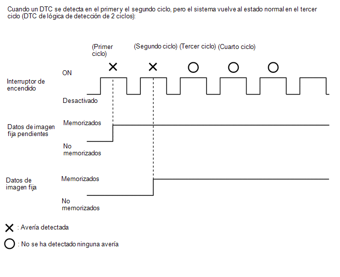
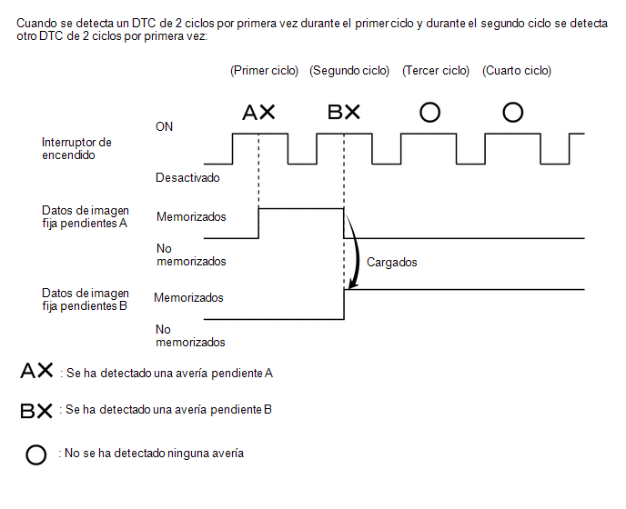
Puede utilizar estos conjuntos de datos para simular el estado del vehículo en el momento en que se produjo la avería. Los datos pueden ayudarle a identificar la causa de la avería y a decidir si es una anomalía temporal o no.

DATOS DE IMAGEN FIJA PENDIENTES

OBSERVACIÓN:

Los datos de imagen fija pendientes se memorizan cuando se detecta por primera vez un DTC de 2 ciclos durante el primer ciclo.

(a) Conecte el Techstream al DLC3.

(b) Coloque el interruptor de encendido en posición ON.

(c) Encienda el Techstream.

(d) Acceda a los siguientes menús: Powertrain / Engine and ECT/Trouble Codes.

Powertrain > Engine and ECT > Trouble Codes

(e) Seleccione un DTC para ver sus datos de imagen fija pendientes.

OBSERVACIÓN:

  • Los datos de imagen fija pendientes se borran cuando se detecta una de las situaciones siguientes.
    • Los DTC se borran con el Techstream.
    • Se desconecta el cable del terminal negativo (-) de la batería.
    • Se han llevado a cabo 40 ciclos con el motor caliente después de volver al estado normal (los datos de imagen fija pendientes no se borrarán con solo restablecer el estado normal del sistema).
  • Una vez memorizados los datos de imagen fija pendientes iniciales, si se detecta un DTC de 2 ciclos durante el primer ciclo y se vuelven a registrar datos de imagen fija pendientes, los datos de imagen fija anteriores se sustituirán por los datos nuevos del DTC detectado en el siguiente ciclo.

LISTA DE LOS DATOS DE IMAGEN FIJA

Powertrain > Engine and ECT

Pantalla del tester

Vehicle Speed

Engine Speed

Calculate Load

Vehicle Load

MAF

Atmosphere Pressure

MAP

Engine Oil Temperature Sensor

Coolant Temp

Intake Air

Engine Run Time

Initial Engine Coolant Temp

Coolant Temp Variation after Waterpump Start

Initial Intake Air Temp

Intake Air Temp Variation after Engine Start

Battery Voltage

Glow Indicator Supported

Glow Indicator

Accel Sens. No.1 Volt %

Accel Sens. No.2 Volt %

Throttle Sensor Volt %

Throttle Sensor #2 Volt %

Throttle Sensor Position

Throttle Motor DUTY

Throttle Air Flow Learning Value(Area 1)

Throttle Air Flow Learning Value(Area 2)

Throttle Air Flow Learning Value(Area 3)

Throttle Air Flow Learning Value(Calculated Value)

Throttle Air Flow Learning Value(Atmosphere Pressure Offset Value)

Throttle Air Flow Learning Prohibit(Intake Air Pressure Malfunction)

Throttle Air Flow Learning Prohibit(Air Fuel Ratio Malfunction)

Throttle Position

ISC Flow

ISC Position

ISC Feedback Value

ISC Learning Value

Electric Load Feedback Val

Air Conditioner FB Val

Low Revolution Control

Neutral Control

N Range Status

Eng Stall Control FB Flow

Fuel Pump Duty

Injector (Port)

Injection Volum (Cylinder1)

Vacuum Pump

Current Fuel Type

EVAP (Purge) VSV

Evap Purge Flow

Purge Density Learn Value

EVAP System Vent Valve

EVAP Purge VSV

Purge Cut VSV Duty

Target Air-Fuel Ratio

AF Lambda B1S1

AFS Voltage B1S1

AFS Current B1S1

A/F Heater Duty B1S1

O2S B1S2

O2S Impedance B1S2

O2 Heater B1S2

O2 Heater Curr Val B1S2

Short FT B1S1

Long FT B1S1

Total FT #1

Fuel System Status #1

Fuel System Status #2

IGN Advance

Knock Feedback Value

Knock Correct Learn Value

Idle Spark Advn Ctrl #1

Idle Spark Advn Ctrl #2

Idle Spark Advn Ctrl #3

Idle Spark Advn Ctrl #4

VVT Control Status #1

VVT Advance Fail

VALVEMATIC Target Angle

VALVEMATIC Current Angle

VALVEMATIC Shaft Sensor Voltage

VALVEMATIC IG OFF

VALVEMATIC IG ON

VALVEMATIC Cranking

VALVEMATIC bef Warm Up

VALVEMATIC aft Warm Up

VALVEMATIC IDM Hi Temp

VALVEMATIC Low(ACT)

VALVEMATIC High(ACT)

Catalyst Temp B1S1

Catalyst Temp B1S2

Starter Signal

Starter Control

Power Steering Signal

Neutral Position SW Signal

Clutch Switch

Stop Light Switch

A/C Signal

Closed Throttle Position SW

Fuel Cut Condition

Immobiliser Communication

TC Terminal

Time after DTC Cleared

Distance from DTC Cleared

Warmup Cycle Cleared DTC

Dist Batt Cable Disconnect

IG OFF Elapsed Time

TC and TE1

Ignition Trig. Count

Cylinder #1 Misfire Count

Cylinder #2 Misfire Count

Cylinder #3 Misfire Count

Cylinder #4 Misfire Count

All Cylinders Misfire Count

Misfire RPM

Misfire Load

Misfire Margin

Catalyst OT MF F/C

Cat OT MF F/C History

Cat OT MF F/C Cylinder#1

Cat OT MF F/C Cylinder#2

Cat OT MF F/C Cylinder#3

Cat OT MF F/C Cylinder#4

Engine Speed (Starter Off)

Starter Count

Run Dist of Previous Trip

Engine Starting Time

Previous Trip Coolant Temp

Previous Trip Intake Temp

Engine Oil Temperature

Previous Trip Eng Oil Temp

Ambient Temp for A/C

Previous Trip Ambient Temp

Engine Start Hesitation

Low Rev for Eng Start

Minimum Engine Speed

Fuel Cut Elps Time

A/F Learn Value Idle #1

A/F Learn Value Low #1

A/F Learn Value Mid1 #1

A/F Learn Value Mid2 #1

A/F Learn Value High #1

Electric Fan Motor

Brake Override System

Idle Fuel Cut

FC TAU

Immobiliser Fuel Cut

Immobiliser Fuel Cut History

Comm with VALVEMATIC

Electrical Load Signal 1

Electrical Load Signal 2

Cruise Main SW

A/F Sensor Determination (worst value) #1

Engine Speed Fluctuation Avg (worst value) #1

Engine Speed Fluctuation Avg (worst value) #2

Engine Speed Fluctuation Avg (worst value) #3

Engine Speed Fluctuation Avg (worst value) #4

    ComprobaciÓn / Borrado De Dtc

    Procedimiento Del Modo De ComprobaciÓn

    Ver más:

    Toyota Corolla Manual de Taller > Sistema ElÉctrico De Control De Los Asientos Delanteros: Medidas De PrecauciÓn
    MEDIDAS DE PRECAUCIÓN PRECAUCIONES PARA DESCONECTAR EL CABLE DEL TERMINAL NEGATIVO DE LA BATERÍA AVISO: Cuando se desconecte el cable del terminal negativo (-) de la batería, reinicie el sistema siguiente después de volver a conectar el cable. Nombre del sistema Consulte el procedimiento Sistema ...

    Toyota Corolla Manual del propetario

    Toyota Corolla Manual de Taller

    © 2024 Copyright www.tocores.net
    0.0135